In medium and large-scale photovoltaic grid-connected power generation systems, the problem of difficult equipment selection is often encountered. How should the equipment be selected to match the entire system so that the system can reach its optimum state? After theoretical analysis and practical application, our company conducted systematic analysis and research on several situations encountered in the current domestic market, and provided the following types of selection principles and methods for reference.
First, the system selection guide
For mid- and large-scale photovoltaic grid-connected power generation systems, multiple parallel operation modes are selected. It is recommended to use the same specification and model power supply (convenient for system group control and data acquisition). Specific selection suggestions are:
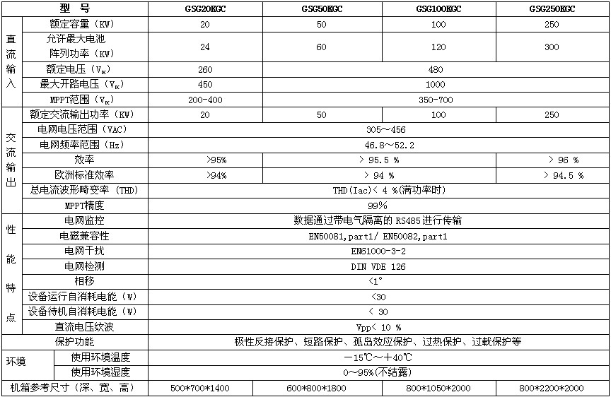
1. Above 1MW photovoltaic power generation system: It is recommended to select multiple GSG250KC power supplies for parallel operation;
2, 500KW to 1MW system: It is recommended to select multiple GSG100KC power supply for parallel operation;
3, 200KW to 500KW photovoltaic power generation system: It is recommended to select multiple GSG50KC parallel operation;
4. Photovoltaic power generation system below 200KW: It is recommended to use multiple GSG20KC or GSG50KC power supplies for parallel operation.
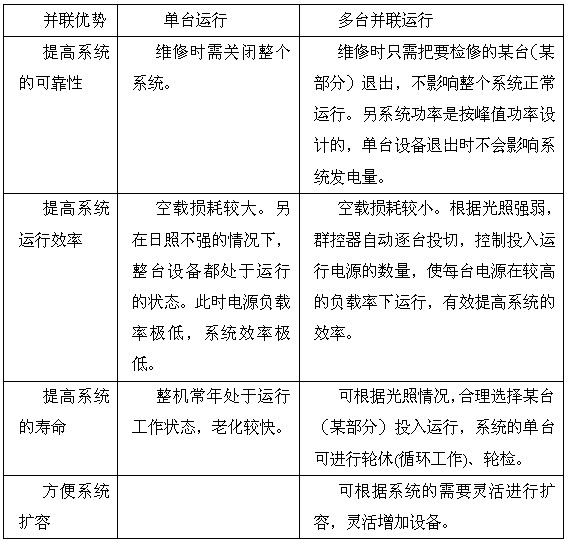
Second, choose the advantages of parallel operation
The use of multiple parallel operations has many advantages. Some of these examples are as follows:
Third, the design process
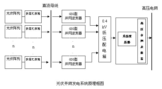
Multiple grid-connected PV inverters are used in parallel to meet the total capacity requirement of the system:
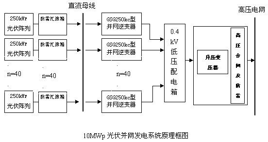
Taking 10MW as an example, the 10MWp photovoltaic power station adopts a modular design scheme and uses 40 sets of 250kW high-power grid-connected inverters with an output voltage of 0.4kV, which can be directly incorporated into a low-voltage power grid or share a set of booster systems, using 10kV or 22kV. Or 35kV and other grid access schemes:
1, system composition
The large-scale grid-connected photovoltaic power generation system is mainly composed of the following parts:
1) Photovoltaic matrix:
Including solar cell components, supporting structures (brackets and foundations, etc.), junction boxes, cables and wires;
2) DC-AC inverter equipment:
Including DC screens, power distribution cabinets, grid-connected inverters, etc.;
3) Step-up grid connection facilities:
Including step-up transformers, outdoor vacuum circuit breakers, high voltage arresters, etc.;
4) Control inspection system:
Including system control devices, data detection and processing and display systems, and remote information exchange equipment;
5) Ancillary facilities:
Lightning protection and grounding protection devices, photovoltaic component cleaning equipment, factories and offices, protective fences, access roads, and roads.
2. Photovoltaic modules:
Choose a photovoltaic module with excellent performance and reliable quality. The series open circuit voltage of the photovoltaic modules must be less than the open circuit voltage of the photovoltaic grid-connected inverters, and the rated voltage of the photovoltaic modules must be in line with the rated voltage of the photovoltaic grid-connected inverters.
3, support structure
The solar array supports are made of hot-dip galvanized steel structure, which can withstand winds above class 8 and have sufficient corrosion resistance. It can be used for 25 years.
4, grid-connected inverter
4.1 Introduction to Performance Features
Photovoltaic grid-connected inverters are digital signal processing using TI's DSP chips as control components. This product has the following outstanding features:
1. Inverter adopts intelligent IGBT (IPM) with fast switching speed and low power consumption as power device. Inverter transformers are also highly efficient and completely isolated, so the inverter has a small distortion of the output waveform; good dynamic characteristics; high inverter efficiency.
2. The control part is a high-speed microprocessor-based control component, so it has features such as output overload, high output and low voltage protection, high anti-interference ability, and high voltage regulation accuracy.
3. Output short-circuit protection, using output circuit detection protection and module saturation pressure drop detection and other dual protection, so as to greatly improve the reliability of short-circuit protection.
4. The output of the inverter is equipped with a radio frequency filter to protect the load (grid) brought by the inverter from high-frequency harmonics.
5. Friendly human interface, through the display panel can clearly understand the system's operating status. For example: DC side voltage, current, grid voltage, current, frequency and other parameters can be displayed.
6. There are various alarm functions, such as grid abnormal alarm, PV module output under-voltage alarm and so on.
7. It has manual input switch for DC input, manual switch for AC mains, switch operation button, etc.
8. Adapt to the harsh grid environment
9. MPPT self-optimizing technology to maximize system power generation
4.2. LCD Display and Menu Introduction
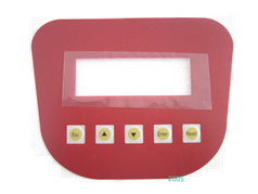
Guanya brand photovoltaic grid-connected inverter power supply has a high degree of intelligence, and it automatically starts and stops every day without human control. At the top of the inverter power supply, there are two main status display LED lights. There are five buttons on the LCD mask (as shown below). Through these indicators and keys, you can know the working status of the inverter power supply and perform the inverter. control.
4.1.1 LED indicator

4.1.2 Key Description
1) The monitoring system unit has a total of five keys, the function name in order are: return key (ESC), up key (), down key (), confirm key (read), reset key (Reset).
2) The first menu in the LCD menu includes: system settings, real-time clock, real-time monitoring, and fault logging.
a, system settings:
language settings
Time adjustment settings
parameter settings
Power generation calibration setting
Grid voltage setting
Protection parameter settings
Restore factory value
b, real-time clock can view the current system year, month, day, week, hour, minute, second.
c. Monitored data in real-time monitoring includes:
Daily power generation
Cumulative power generation
DC voltage
DC
Network side voltage
Net side current
Grid frequency
Output Power
Current ambient temperature
Total hours run
d, fault records:
DC overvoltage
DC undervoltage
DC overcurrent
Output overvoltage
Output undervoltage
Output overcurrent
Abnormal temperature
Abnormal frequency
3) The key functions are described as follows: Press the "back key" to return to the previous menu; the "up" and "down" keys can be used to select the menu to be viewed and different pages in the same level menu, the selected menu Display in reverse format; press "Confirm" to enter the next menu of the selected menu; select the option in the system settings, and then click "Confirm" to confirm, if the modification is successful, it will prompt "Modify Success!†indicates the completion of the modification; first select the option to be set and click “Confirmâ€, and then use the “up†(ie add 1) and “down†(ie minus 1). Add 1 and decrement 1 operation; press “confirmation button†at the end to confirm the parameters and complete the modification.
4) The password only works for "System Settings". If the system has a password, you must enter the 8-digit password to access the above two menus. You can cancel the password and change the password through “System Settingsâ€. No password is set at the factory. The operation to modify the password is as follows: enter the "System Settings - Password Settings - Change Password", and then through the "up" (in this case represents 1) and "down" (in this case 0) password settings by This shows that the password is an 8-digit number composed of 1s and 0s. In the process of password modification, you can delete the just entered number (0 or 1) through the “return buttonâ€. When the password is filled with 8 bits, it will automatically prompt the next step. You do not need to press "Confirm". You need to enter the password twice to change the password. If the two passwords are inconsistent, the system prompts “inconsistent passwordâ€; otherwise, “modification is successful†will be prompted. Press “return button†at this time to exit the password modification status.
5) Once the password is lost, please inform my company, our company can crack through related software.
4.3. Remote Control Section Description:
Grid-connected power supply can achieve the following control through close and remote connection with PC (via RS485 interface):
☆ DC current, DC voltage, grid voltage, grid-side current, output power, etc. are displayed on the PC.
☆ Display the amount of electricity generated on the day, cumulative power generation, etc. on the PC;
☆ Fault alarm: The faults appearing on the grid-connected inverter power supply can be transmitted to the PC through the RS485 interface.
☆ View the current time information;
☆ The grid-connected power supply can be remotely controlled in the control software on the PC to adjust the control parameters of the grid-connected power supply.
4.4, special upper computer software
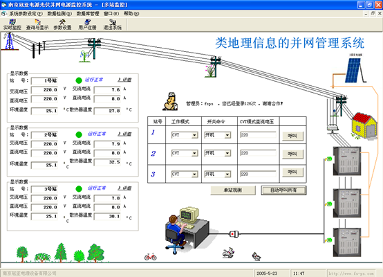
The software provides users with an on-line system that supervises power supply and power consumption equipment remotely and cooperates with our company's photovoltaic grid-connected inverter power generation system to perform real-time data display and processing, system function analysis, system accident recall, and various documents. Backup, user level selection, remote specific function control, new user power usage learning, online help and other functions.
Specific function
A: Real-time data display and processing
Using the call response protocol, online real-time data display.
For real-time data processing, you can refer to the comparison expert system views to provide the best power usage optimization solution.
For non-real-time data such as system power, accident records, etc., according to the power system acquisition cycle, do timing acquisition and packaging. Process and back up within the set time period of the system's corresponding acquisition cycle.
Powerful geographic information management system design.
1). Multiple stations monitor the main interface at the same time
2). Single station observation
3). Data processing is comprehensive, profound, and diversified.
B: accident recall
Including offline accidents and online accidents. Provide more convenience to customers who cannot turn on the computer for a long time.
Have detailed accident records (accurate to seconds, displayed in time period, and record all operating parameters of the system for future reference) multiple query methods (by site, by time, by date and combination method)
Report generation and printing
Data software backup and data hardware backup.
C: very powerful alarm function
With alarm parameter setting, alarm parameter display and hold. Provide voice (content can be selected to meet the individual needs, while providing pc internal buzzer alarm, saving energy for the user.), Light, SMS, mail, telephone and other alarm methods.
D: safe mode
For users: Provides rights management, password login, error-free operation design, free upgrade of power knowledge database, new power users learn video data.
For the power supply equipment: real-time control, comprehensive and specific parameters (network-based alarms provide nearly 20 kinds of alarm design), anti-misoperation handling.
E: Additional features, user-friendly design
Humane interface design
Data display diversity
Convenient window arrangement
Avoid repeated design
Various date and time display
F: Constant innovation, strive for perfection (wireless monitoring introduction)
System specification:
The device only needs to insert a SIM card to complete remote bi-directional data transmission in the form of short messages or data over the GSM network. The remote terminal can be a PC, a mobile phone or other mobile device.
The application of GSM network in short messages has the advantages of wide coverage, reliable transmission, and low price. Suitable for applications that require frequent transmission of small traffic data and unsuitable for laying lines.
The current system has been able to support multi-station control.
4.5, chassis shape
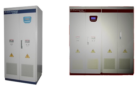
4.6, technical parameters
5, PV array lightning combine box
In order to reduce the connection line between the PV array and the inverter and to facilitate future maintenance, the system is equipped with a solar array lightning protection confluence box in the outdoors. The confluence box can be directly installed on the battery bracket.
The performance characteristics of the PV array lightning arrester box are as follows:
Outdoor wall-mounted installation, waterproof, anti-rust, sunscreen, anti-salt spray and anti-acid mist, fully meet the outdoor installation and use requirements;
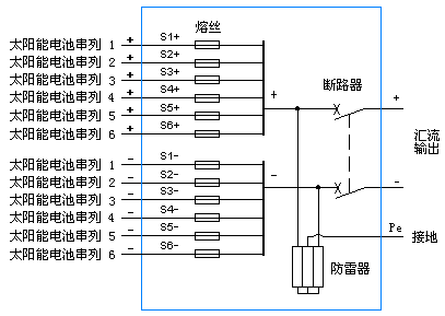
Each PV array is equipped with a special high-voltage DC fuse for photovoltaic protection, and its withstand voltage is DC1000V;
DC output bus is equipped with a special high-voltage arrester for photovoltaics between the positive pole and the negative pole, and between the positive pole and the negative pole.
The DC output bus end is equipped with a special high-voltage DC circuit breaker that can be broken. The circuit breaker is ABB brand;
The electrical block diagram of the PV array lightning protection bus box is shown in the following figure:
6, DC screen
The DC panel adopts the parallel connection of busbars. The convergence output of all the convergence boxes is integrated into the DC panel. The DC panel is used for centralized monitoring and management, and the operation and maintenance are convenient. The DC input of each inverter is DC-distribution and DC-collection from the DC screen bus.
Even if a certain photovoltaic grid-connected power source fails, the photovoltaic energy can still be fully utilized by other photovoltaic grid-connected power sources. It does not occur that the failure of one grid-connected power source results in the inefficient use of the corresponding photovoltaic component energy. Fully increase the utilization of photovoltaic energy, reflecting environmental protection and high efficiency.
7. Step-up transformer (boost station)
Voltage 0.4 kV/35 kV; (Determine the grid connection voltage according to requirements);
Capacity (configured according to system capacity);
The high-voltage grid-connected access plan must be designed by a professional electric power design institute and be constructed by a professional construction team.
8, control and detection system
Collect and record operating data, such as solar radiation and other meteorological data, electrical performance parameters, equipment working status, etc.;
Perform related control operations, such as meeting inverter output, solar cell array output, and tracking control;
System fault automatic protection function, record and save fault information, send alarm signal;
Remote data monitoring.
The monitoring system configuration configures a professional environmental data monitor for industrial computers and Guanya Power, and Guanya Power's multi-machine monitoring software. Remote monitoring requires network support. Scalable large-screen display of real-time power generation data.
9. Buildings (computer room and office area)
The design and construction specifications for buildings are strictly implemented in accordance with national standards. The lightning protection design and construction specifications for computer rooms strictly comply with the national standard GB50174-1993, and the lightning protection design and construction specifications for office areas strictly implement the national standard GB50057-94.
10, lightning protection and grounding protection
10.1 Lightning protection measures for all buildings (computer room and office area) of photovoltaic grid-connected power stations shall strictly comply with national standards:
Building lightning protection design specification: "GB50057-94"
Computer room design specification: "GB50174-1993"
10.2 Integrated lightning protection measures are adopted to avoid lightning strikes on buildings or to minimize the damage caused by lightning strikes. The comprehensive lightning protection design plan should include two aspects: direct lightning protection and induction lightning protection. The absence of any aspect is incomplete, flawed, and potentially dangerous.
10.2.1 Protection against direct lightning: Use lightning rods, lightning protection nets, lightning protection strips and good grounding systems. Its purpose is to protect buildings from lightning damage and provide a relatively safe environment for people and equipment in buildings.
10.2.2 Inductive Ray Protection: At present, there are two main ways that computers and other electronic devices are subjected to lightning induced high voltage damage:
(1) Radiated induced lightning strikes: Strong lightning electromagnetic fields cause equipment damage through radiation or induction;
(2) Inductive lightning high-voltage pulses transmitted from various lines, such as power supply lines, signal lines, and control lines, damage computers and other electronic devices.
Therefore, adopt appropriate measures:
(1) Take electromagnetic shielding measures;
(2) Installation of surge overvoltage protectors, including power supply systems and signal systems;
(3) Equipotential processing;
(4) Good grounding.
11, site path
11.1 Convenient for installation, commissioning, operation, maintenance and cleaning;
11.2 meet other relevant requirements.
12, protective fence
Sufficient height and strength to meet protection requirements;
There is a distance from the PV array to prevent obstruction.
Transmission And Distribution Pole
Steel poles are commonly used to carry several types of electric power lines, distribution lines and lighting system. Distribution lines carry power from local substations to customers. They generally carry voltages from 4.6 to 33kV for distances up to 30 miles, and include transformers to step the voltage down from the primary voltage to the lower secondary voltage used by the customer. A service drop carries this lower voltage to the customer's premises.
Transmission And Distribution Pole,Transmission Line Poles,Power Transmission Line,Galvanized Transmission and Distribution Pole
Yixing Steel Pole International Trading Co., Ltd , https://www.yx-steelpole.com