Toshiba
1. LCD TV repair process
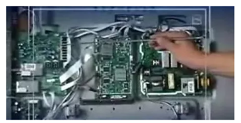
1. The power board only provides a 5V or 3.3V power supply to the CPU during standby, and other 12V.18V.24V.9V voltages will not appear until STANDBY is turned on. At this time, the CPU needs to send a high level 5V or 3 3V to the power board, the power board starts 12V, 9V, 18V.24V voltage after receiving the voltage from the CPU. If these voltages of the power board are normal, basically confirm that the power board is OK.
2. After the power-on level of the CPU board is issued, the 5V voltage provided by the power board is sent to some chips for power supply through some 3.3V, 2.5V, 1.8V SMD regulators. Do n’t underestimate these low voltages. Often, these voltages are a little bit higher (0.7V) and black screen without grating faults will occur. Usually the damaged ones are the power supply filter capacitors that are degraded, or the main killers that have strange faults after aging, generally The power supply of the LCD decoding integration (digital conversion IC) is around 3.3V and 1.8V, and the power supply of the registers connected to the decoding integration is 2.5V. When the LCD is used for about 1 year, these decoding integrations are often prone to virtual Welding failure, this time test everyone's welding skills, practice has proved that part of the repair after repairing the fault.
3. The black screen failure after no grating or grating flash is also the most common type of LCD failure. This failure can generally be judged by measuring the voltage. After the remote control is turned on, check whether each power supply of the power board is normal, and then measure the Is the voltage of the ON / OFF pin of the connection line to the backlight board high level 3.3V, and then check whether the voltage of the PWM pin is also around 3.3V, if it is normal, it should be that the backlight board that comes with the display is faulty, If these two voltages are not available, the problem is that the decoding integration does not work or the software does not run, and the CPU board must be repaired.
The above is just a small part of the experience of repairing flat-screen TVs. If you want to repair fast, you still need to spend more time to hone. I hope everyone can become a master of repairing flat-screen LCD TVs.

Second, the common fault judgment method of LCD TV
Now that LCD TVs are the main products of major manufacturers, ordinary CPT TVs have gradually withdrawn from the market, so it is imperative to master the skills of repairing LCD TVs as a maintenance staff. The following is my experience in maintenance Exchange, I hope that more such articles will appear in the future.
To repair the LCD, you must learn to judge which part is faulty. This is the first step. Let me talk about the main faults and parts of the LCD TV.
1. There is no image and no sound when booting, the power light flashes and becomes solid, and the screen flashes white light at the moment of booting. This failure is mostly due to the damage of the backlight driver board. However, it has been encountered that the lamp in the screen is damaged during maintenance .
2. There is a flower screen (mosaic) when the machine is turned on, and the sound is normal. The first of this phenomenon is the bad digital board (the via hole is not open or the IC is not in good contact). The second is the bad connection of the internal wiring.
3. There is no power on and the power light is off. The first one is that the power board is broken, and the second one is that the CPU part is not working properly.
4. Flashing lights can not be turned on: CPU bus does not work normally or the boot program IC (BIOS) is bad, and the contact between the "BIOS" IC and the CPU is bad

3. Judgement and maintenance of each component board of plasma screen
Like ordinary TV sets, the high-fault parts of plasma TV sets are the power board and the driver board. The reason is that these parts are working in high voltage and high current state. Since the current maintenance of plasma TVs is board-level maintenance, in actual inspection, it is only necessary to determine the faulty component board or circuit board, and it is not necessary to repair the components on the component board And replace. Just because: on the one hand, most of the components in the plasma TV circuit board are imported, which are not available in China or not provided by the manufacturer of the screen; on the other hand, the various circuit boards in the plasma TV are multi-layer Structure, maintenance under non-factory conditions, it is easy to create new failures for the circuit board due to poor assembly and disassembly, so the current plasma TV,
The maintenance of LCD TVs, the entire industry is performing board-level maintenance, which is to replace the entire component board.
When repairing, testing, and disassembling the circuit of the PDP screen, you must pay attention to whether the large-capacity capacitor has been discharged? And pay attention to the difference between the cold ground and the hot ground when detecting the voltage, and at the same time, we must strictly pay attention to the anti-static or ESD.
Fourth, the judgment and detection of the power board
First of all, you should check whether the output voltage of the power board is the same as the one marked on the sticker on the upper right corner of the screen (show this sticker to everyone at this time). If the measured voltage is different from the one marked on the screen, then Most likely:
â‘ The power board itself is damaged, causing the voltage to be different from what is marked on the screen;
â‘¡ There is a problem with the load of the power board, which leads to the inconsistency between the voltage output by the power board and the label on the screen. We can first detect the voltage value of each socket output by the power board, and find that the voltage value on that socket is abnormal, unplug the plug line on the socket, and disconnect it from the subsequent circuit, then test the power socket If the voltage is normal, it means that there is a problem with the circuit board of the next stage, otherwise it is on the power board itself. One thing to note is that the VS voltage is output on both sockets here (the location of these two sockets is pointed out at this time), so if the VS voltage is still abnormal when the next plug is unplugged, It is also necessary to unplug the plug with VS voltage on the other side, so as to judge whether it is the power board or the circuit board problem of the subsequent stage.
In actual maintenance, the most common failure of the power board is that there is no drive voltage output or the drive voltage is too low, resulting in a black screen (black screen refers to the entire screen is not bright, or there is sound or no sound). By testing it, you can find that the VS drive voltage has dropped significantly, while the VSC drive voltage has dropped to about 0V. The power board of PS42D8 can be tested without actual load during actual maintenance, so the maintenance will be very convenient. When we suspect a problem with the power board, we can unplug all plugs of the entire power board assembly, remove the power board assembly, and short-circuit the third and fourth pins from the left of the CN802 (or CN9004) socket on the power board , And then connect the power board with 220V power supply (demonstration is needed at this time). If the power board parts are good, then after power on, all its sockets will be output and marked on the screen, printed on the printed board The same voltage (with a certain deviation, but the deviation value is very small), as long as there is a voltage or a group of voltages that are not the same, the power board component is bad.
5. Trouble shooting of driver board, Y board and logic board
If the X driver board of the screen is broken, the following faults may occur:
1. The image is very dark or has no contrast or poor layering;
2. A black screen may also appear;
3. Colored patches on the image. When it is suspected that the X driver board is broken, the board can be disconnected from the circuit. If the X driver board is removed, the image is almost unchanged, that is, the X driver board is installed and not installed, almost the same At this time, the X driver board may be broken. Or a good X driver board can replace it. Whether the fuse on the X drive board (the location of the fuse is pointed out at this time) can also become a basis for damage.
The above content is provided by Toshiba , choose Toshiba when you buy electrical appliances ! GO Jiaju Hefei Station opened!
Isuzu Supply Module,Isuzu Supply Module 8982264733,ISUZU Injector,ISUZU 4HG1 Injector
JINING SHANTE SONGZHENG CONSTRUCTION MACHINERY CO.LTD , https://www.sdkomatsugenuineparts.com