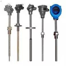
(1) Sudden increase in temperature: This fault is mostly caused by thermal resistance (thermocouple) open circuit, loose terminal, (compensation) wire breakage, temperature failure, etc. At this time, it is necessary to know the location and wiring layout of the temperature. Using the multimeter's resistance (millivolt) file to measure several sets of data at different locations can quickly identify the cause.
(2) Sudden temperature decrease: This fault is mostly caused by short circuit of thermocouple or RTD, short circuit of conductor and temperature failure. It is necessary to start from the weak points that are easy to malfunction, such as the wiring port and the corner of the wire, and check them one by one. The temperature of the site rises, and the total control indication does not change, mostly due to the liquid (water) with a lower boiling point at the measuring component.
(3) Large fluctuations in temperature or rapid oscillation: At this time, the process operation should be mainly checked (inspection adjustment system participating in the adjustment).
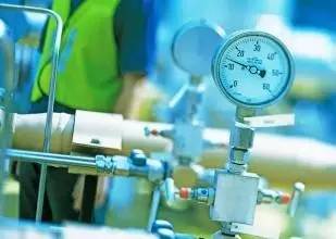
(1) The pressure suddenly becomes smaller, becomes larger or there is no change in the indication curve: at this time, the transmitter pressure system should be checked to check whether the root valve is blocked, whether the pressure pipe is unblocked, whether there is abnormal medium inside the pressure pipe, and the sewage wire Block and drain valve leaks. Winter media freezing is also a common phenomenon. The transmitter itself is unlikely to malfunction.
(2) Pressure fluctuations: This situation must first be combined with the craftsman, usually caused by improper operation. The parameters involved in the adjustment should mainly check the adjustment system.
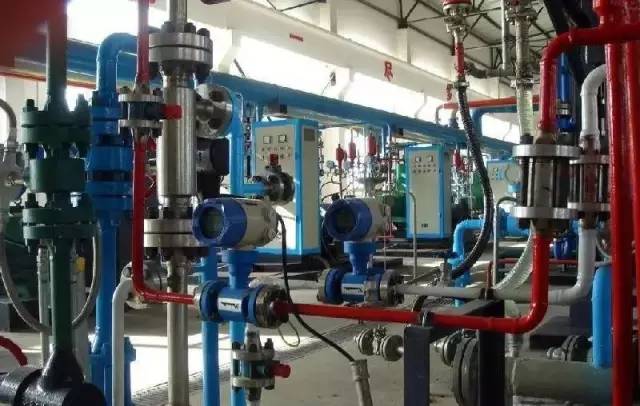
(1) The minimum flow indication value: generally caused by the following reasons: the detection component is damaged (zero is too low; there is a problem; the circuit is short-circuited or open; the positive pressure chamber is blocked or leaked; the system pressure is low; the parameters involved in the adjustment are also checked Regulators, regulators and solenoid valves.
(2) Maximum flow indication: The main reason is that the negative pressure chamber pressure system is blocked or leaking. It may not be possible for the transmitter to be calibrated.
(3) The flow fluctuation is large: the flow parameter does not participate in the adjustment, generally the process reason; if it participates in the adjustment, the PID parameter of the regulator can be checked; the parameter of the isolation tank is used to check whether there is a bubble in the pressure-collecting pipe, and the positive and negative pressure are pressed. Whether the liquid in the tube is the same.
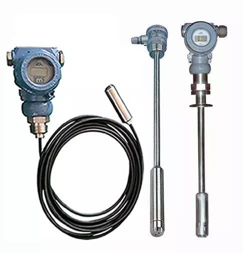
(1) The liquid level suddenly becomes larger: mainly check whether the pressure-reducing system of the negative pressure chamber of the transmitter is blocked, leaked, gas-collected, and liquid-deficient. The specific method of filling is: first stop the table according to the stop table order; close the positive and negative pressure root valve; open the positive and negative pressure drain valve to release pressure; open the double chamber balance container filling liquid plug; open the positive and negative pressure chamber drain plug; The liquid level indication is maximum at this time. Close the drain valve; close the drain plug of the positive and negative pressure chamber; slowly fill the double chamber balance container with the same medium, at this time, open the drain wire to block the exhaust; until it is full, open the positive pressure chamber plug and change The transmitter indication should return to zero. The transmitter is then applied in the order in which it was posted.
(2) The liquid level suddenly becomes small: mainly check whether the positive pressure chamber pressure system is blocked, leaked, gas collected, liquid-deficient, and the balance valve is closed. The specific method for checking whether the pressure guiding system is unblocked is to stop the transmitter, open the drain valve, and check the sewage discharge (except for the medium that cannot be leaked).
(3) The indication of the general control room does not match the liquid level at the site: firstly, it is judged whether the liquid level gauge is faulty. At this time, the liquid level can be artificially increased or decreased, and the cause of the problem is analyzed according to the situation of the site and the general control indication (field level gauge The root valve is closed, blocked, and leaky, which may cause on-site indications to be inaccurate). The liquid level can be restored by checking the zero point, the range, and the filling. If it is still not normal, you can notify the process technician to reset the transmitter and adjust the pressure on-site.
(4) Frequent fluctuation of liquid level: Firstly, in combination with the process personnel to check the feeding and discharging conditions, after determining the normal state of the process, it can be stabilized by adjusting the PID parameters. The specific method is: adjust the valve to the manual state, first adjust the set value and the measured value to make the liquid level fluctuation smooth, and then slowly adjust the opening of the regulating valve, so that the liquid level slowly rises or falls, meets the process requirements, and then adjusts The set value is consistent with the measured value, and the regulating valve is automatically activated after the parameter is stabilized.
In short, once the instrument parameters are found to be abnormal, first of all, combined with the process personnel, starting from the two aspects of the process operating system and the field instrument system, comprehensive consideration, careful analysis, especially considering the relationship between the measured parameters and the control valve, the fault will be divided Step segmentation judgment, it is easy to find out the problem, solve the problem with the right medicine.
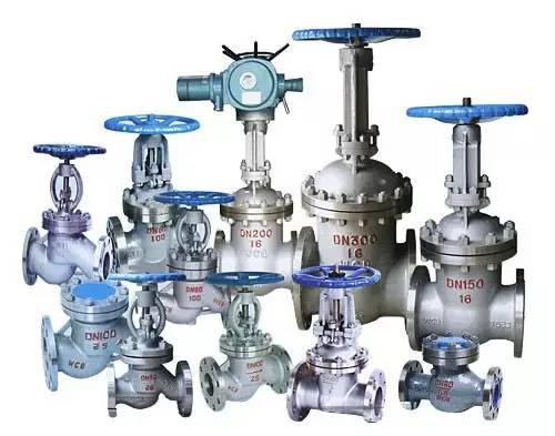
Valve type safety and use can be divided into the following
1. Exhaust valve: Exclude excess gas in the pipeline, improve pipeline efficiency and reduce energy consumption.
2. Diverter: Distribute, separate, or mix media in the pipeline.
3. Safety valve: Prevent the pressure of the medium in the pipeline or device from exceeding the specified value, so as to achieve the purpose of safety protection.
4. Check valve: prevent the medium in the pipeline from flowing backwards.
5. Shut-off valve: Turn on or cut off the circulation of the medium in the pipeline.
6, regulating valve: adjust the pressure, flow and other parameters of the medium.
Now we mainly introduce the self-standing regulating valve and the pneumatic regulating valve.
1. Working principle of self-operated pressure regulating valve (post-valve pressure control)
The pre-valve pressure P1 of the working medium passes through the throttle after the valve core and the valve seat, and becomes the post-valve pressure P2. P2 is input into the lower chamber of the actuator through the control line and acts on the top plate. The generated force is balanced with the reaction force of the spring, which determines the relative position of the valve core and the valve seat, and controls the pressure behind the valve. When the post-valve pressure P2 increases, the force acting on the top plate of P2 also increases. At this time, the force of the top plate is greater than the reaction force of the spring, so that the valve core is closed to the position of the valve seat until the force of the top plate is balanced with the reaction force of the spring. At this time, the flow area of ​​the valve body and the valve seat is reduced, and the flow resistance is increased, so that P2 is lowered to a set value. Similarly, when the post-valve pressure P2 is lowered, the action direction is opposite to the above, which is the working principle of the self-operated (post-valve) pressure regulating valve.
2, the working principle of self-operated pressure regulating valve (pre-valve pressure control)
The pre-valve pressure P1 of the working medium passes through the throttle after the valve core and the valve seat, and becomes the post-valve pressure P2. At the same time, P1 is input into the upper chamber of the actuator through the control pipeline and acts on the top plate. The generated force is balanced with the reaction force of the spring, which determines the relative position of the valve core and the valve seat, and controls the pressure before the valve. As the pre-valve pressure P1 increases, the force acting on the top plate by P1 also increases. At this time, the force of the top plate is greater than the reaction force of the spring, so that the valve core moves away from the valve seat until the force of the top plate is balanced with the reaction force of the spring. At this time, the flow area of ​​the valve body and the valve seat is reduced, and the flow resistance is reduced, so that P1 is lowered to a set value. Similarly, when the pre-valve pressure P1 is lowered, the action direction is opposite to the above, which is the working principle of the self-operated (pre-valve) pressure regulating valve.
3. Working principle of self-operated flow regulating valve
After the controlled medium is input to the valve, the pre-valve pressure P1 is input to the lower membrane chamber through the control line, and the pressure Ps after the throttling of the throttle valve is input to the upper membrane chamber. The difference between P1 and Ps is ΔPs=P1-Ps, which is called effective pressure. . The thrust generated by P1 acting on the diaphragm and the thrust difference generated by Ps acting on the diaphragm are balanced with the spring reaction force to determine the relative position of the spool and the valve seat, thereby determining the flow rate through the valve. When the flow rate through the valve increases, that is, ΔPs increases, and as a result, P1 and Ps act on the lower and upper membrane chambers respectively, so that the valve core moves toward the valve seat, thereby changing the flow area between the valve core and the valve seat, so that The Ps increases, and the increased thrust of the Ps acting on the diaphragm plus the spring reaction force and the thrust of the P1 acting on the diaphragm balance the new position to achieve the purpose of controlling the flow. On the contrary, the same reason.
Pneumatic control valve uses compressed air as the power source, cylinder as the actuator, and drives the valve by means of electric valve positioner, converter, solenoid valve, limit valve and other accessories to realize switching or proportional adjustment, receiving industry The control signals of the automation control system are used to complete various process parameters such as flow, pressure, temperature and liquid level for adjusting the pipeline medium.
1. Classification of pneumatic control valves
The pneumatic regulating valve operates in two types: air opening type and air closing type. Air to Open is when the air pressure on the diaphragm head increases, the valve moves in the direction of increasing opening. When the upper limit of the input air pressure is reached, the valve is fully open. Conversely, when the air pressure is reduced, the valve moves in the closing direction, and when there is no input air, the valve is fully closed. Therefore, the gas-open valve is sometimes called the Fail to Close FC. The air to close action direction is just the opposite of the air open type. When the air pressure increases, the valve acts in the closing direction; when the air pressure is reduced or not, the valve is in the opening direction or fully open. Therefore, it is sometimes called Fail to Open FO. The air opening or closing of the pneumatic regulating valve is usually achieved by the different positive and negative actions of the actuator and the different assembly of the valve state structure.
2, several common technical terms
The regulating valve has two parts: an actuator and a valve body part. The regulating valve generally adopts a pneumatic film actuator, and its action mode is positive or negative. When the signal pressure increases, the push-down is the positive acting actuator. When the signal pressure increases, the push-up moves up to the reaction actuator. The valve body parts are divided into two types: positive and reverse. When the valve stem moves down, the flow area of ​​the valve core and the valve seat is reduced to be a positive-loading type, and vice versa. The mode of action of the regulating valve is divided into two types: gas opening and gas closing. The gas opening and gas closing are combined by the positive and negative action of the actuator and the positive and negative assembly of the valve body parts.

The gas opening of the regulating valve or the gas shut-off is considered in many aspects. Firstly, the process safety is taken into consideration. After determining the gas shut-off or the gas opening, the effect of the actuator is determined, and finally the positive and negative loading of the valve body is determined. The combination is as described above.
The positive acting actuator refers to the movement of the actuator push rod toward the valve body when the gas pressure on the diaphragm increases; the reaction actuator refers to the movement of the actuator push rod away from the valve body when the gas pressure on the diaphragm increases; and the air opening (air to open), air to close type valves are completely different concepts. The positive acting actuator and the positively mounted (reversely mounted) valve are pneumatically closed (air open); conversely, the reaction actuator and the reverse mounted (positively mounted) valve can be pneumatically closed (air open).
The positive and negative action of the positioner corresponds to the air opening and air closing of the control valve you have purchased. That is to say, in order to achieve the negative feedback of the entire valve itself. The positive and negative effects of the regulator are used to set the negative feedback of the entire control loop. When the regulator is automatically activated, the positive and negative effects of the regulator can be embodied.
The positive and negative action of the valve positioner is determined according to the gas opening and closing of the regulating valve. The positive and negative effects of the regulator are determined according to the characteristics of each link of the control circuit, and the control circuit must be guaranteed to meet the control requirements. For example, to implement negative feedback control, in the automatic control system, the adjusted parameters often deviate from the set value due to the influence of interference, that is, the adjusted parameters produce deviations:

For the regulator, according to the uniform regulation, if the measured value increases, the regulator output increases, and the regulator amplification factor Kc is negative, the regulator is called a positive acting regulator; when the measured value is increased, the regulator output is decreased, When Kc is regular, the regulator is called a reaction regulator.
3, the choice of pneumatic control valve
Before any control system is put into operation, the positive and negative effects of the regulator must be correctly selected so that the direction of the control action is correct. Otherwise, instead of negative feedback but positive feedback in the closed loop, it will continuously increase the deviation and eventually The controlled variable will be directed to the highest or lowest limit.
In a single-loop control system, as long as the product of the amplification factor Kc of the regulator, the amplification factor Kv of the regulating valve, and the amplification factor Ko of the controlled object is positive, negative feedback control can be realized. Regulators, regulating valves and object amplification factors are specified as follows:
(1) The sign of the amplification factor of the regulator; for the regulator, according to the uniform regulation, the measured value increases, the output increases, and the regulator amplification factor Kc is negative, which is called positive action. The measured value increases, the output decreases, and Kc is positive, which is called a reaction.
(2) The sign of the amplification factor of the regulating valve; the amplification factor Kv of the regulating valve is defined as the positive opening valve Kv and the closing valve Kv being negative.
(3) The sign of the magnification factor of the object; the magnification factor Ko of the object is defined as: if the manipulated variable increases, the controlled variable also increases, Ko is positive; the manipulated variable increases, the controlled variable decreases, and Ko is negative. It can be seen that the method for determining the positive and negative effects of the single-loop control system regulator is as follows: firstly determine the sign of the object magnification coefficient Ko, and then determine the positive and negative of the amplification factor Kv of the regulating valve according to whether the valve selection is air-open or gas-closed. No. Finally, the product of Kc, Kv, and Ko should be positive to determine the mode of action of the regulator.
In short, the choice of gas-opening is based on the safety perspective of process production. When the air supply is cut off, is the control valve safe in the closed position or in the open position? For example, in the combustion control of a furnace, the regulating valve is installed on the fuel gas pipe to control the supply of fuel according to the temperature of the furnace or the temperature of the heated material at the outlet of the furnace. At this time, it is more safe to use the gas-opening valve, because once the gas source is stopped, the valve is closed more than the valve is fully open. If the air supply is interrupted and the fuel valve is fully open, there is a danger of excessive heating. Another example is a heat exchange device cooled by cooling water. The hot material is cooled by heat exchange with the cooling water in the heat exchanger. The regulating valve is installed on the cooling water pipe, and the temperature of the heat exchanged material is used to control the amount of cooling water. When the air supply is interrupted, it is safer to make the regulating valve in the open position. The gas-closed (ie FO) regulating valve should be used.
4, the maintenance of pneumatic control valve
Pneumatic control valves are of great significance for ensuring the normal operation and safe production of process equipment. Therefore, it is necessary to strengthen the maintenance of the pneumatic regulating valve.
A. The key inspection site during maintenance
a. Check the inner wall of the valve: In the case of high pressure difference and corrosive medium, the diaphragm of the inner wall of the valve and the diaphragm valve are often subjected to the impact and corrosion of the medium, and the pressure and corrosion resistance must be checked.
b. Check the valve seat: the inner surface of the thread for fixing the valve seat is susceptible to corrosion and the valve seat is slack due to the infiltration of the medium during operation;
c. Check the valve core: the valve core is one of the movable parts of the regulating valve, which is seriously damaged by the medium. During the inspection, it is necessary to carefully check whether the various parts of the valve core are corroded and worn, especially in the case of high pressure difference, the valve The cavitation caused by cavitation of the core is more serious. Damaged spools should be replaced; check seal packing.
B, routine maintenance of pneumatic control valve
When the regulating valve is made of graphite-asbestos, the lubricating oil should be added to the packing for about three months to ensure the flexibility of the regulating valve. If it is found that the packing pressure cap is pressed very low, the filler should be replenished. If the polytetrafluoroethylene dry packing is found to be hardened, it should be replaced in time; the operation of the regulating valve should be paid attention during the inspection, and the valve position indicator and regulator should be checked. Whether the output is consistent; check the gas source for the regulating valve with the positioner, and find the problem in time; always keep the health of the regulating valve and the complete and easy use of all components.
(1) Failure and cause of the valve not working
1. No signal, no air source.
the reason:
1 gas source is not open;
2 The gas source is dirty, causing the gas source pipe to clog or the filter and the pressure reducing valve to be clogged (special attention to the winter air source with water icing);
3 compressor failure makes the air source pressure low;
4 gas source manifold leaks.
2. There is a gas source and no signal.
the reason:
1 regulator failure, 2 gas source tube leakage; 3 valve positioner leakage; 4 control valve diaphragm damage.
3. The positioner has no air supply.
the reason:
1 filter blocked; 2 pressure relief valve failure; 3 pipeline leakage or blockage.
4. The positioner has no air supply output.
the reason:
1 The orifice of the positioner is blocked; 2 the amplifier fails; 3 the nozzle is blocked.
5. There is signal, no action.
the reason:
1 spool is detached, 2 spool is stuck; 3 stem is bent; 4 actuator spring is broken.
(2) Failure and cause of unstable operation of the regulating valve
1. The gas source pressure is unstable.
the reason:
1 gas source manifold leakage; 2 pressure relief valve failure.
2. The signal pressure is unstable.
the reason:
1 The time constant of the control system (T=RC) is not appropriate; 2 The regulator output is unstable.
3. The air supply pressure is stable and the signal pressure is stable, but the action of the regulating valve is still unstable.
the reason:
1 The ball valve of the amplifier in the positioner is not tightly damaged by the dirt, and the output oscillation occurs when the air consumption is particularly increased;
2 The nozzle flapper of the amplifier in the positioner is not parallel, and the baffle cover cannot cover the nozzle;
3 output tube, line leakage; 4 actuator rigidity is too small.
(3) Faults and causes of regulating valve vibration
1. The regulator valve vibrates at any opening.
the reason:
1 support is unstable; there is vibration source near 2; 3 valve core and bushing wear seriously.
2. The regulator valve vibrates as it approaches the fully closed position.
the reason:
1 The regulating valve is selected to be large, and is often used at a small opening; 2 The flow direction of the single seat valve is opposite to the closing direction.
(4) Faults and causes of slow operation of the regulating valve
1. The valve stem is slow to operate in only one direction.
the reason:
1 diaphragm leakage in pneumatic diaphragm actuator; 2 "O" seal leakage in the actuator.
2. The valve stem is dull when reciprocating.
the reason:
1 There is stickage in the valve body; 2 There is a problem with the packing, the pressure is too tight or needs to be replaced.
(5) Faults and causes that the regulating valve is closed but the leakage is large
1. The leakage is large when the valve is fully closed.
the reason:
1 The valve core is worn, the internal leakage is serious, and the 2 valves are not adjusted well.
2. The valve does not reach the fully closed position.
the reason:
1 The pressure difference of the medium is too large, the rigidity of the actuator is small, the valve is not tight; 2 the valve has foreign matter; 3 the bush is sintered.
(6) The flow adjustable range becomes smaller
The main reason is that the valve core is corroded and becomes smaller, so that the adjustable minimum flow rate becomes larger.
Vortex Spring,Coil Springs,Vortex Coil Spring,Vortex Coil Spring Processing
Dongguan Jiufukai Hardware Products Co., Ltd , https://www.jfkspring.com