[ Huaqiang Security Network News ] 
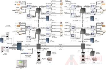
Everyone should know the use of the building intercom system , but it may not be easy to understand on the debugging and installation. Let me introduce you to the following:

1. Preparation before installation of the equipment 1. Before installing the equipment, it is necessary to carry out a comprehensive inspection of all the lines of the system, whether there is a disconnection or short circuit phenomenon;
2. After confirming that there is no fault in the line of the whole system, the equipment can be installed, and the joints of the wiring must be soldered;
3. When installing the equipment, it must be wired in strict accordance with the instructions attached to the product or the installation manual.
Second, the system before the power-on commissioning inspection 1, after the equipment is fully installed, you must fully check the wiring of each part is correct; if there is a connection error may cause the entire system can not work properly.
2. In particular, check whether the power cord is connected incorrectly, and whether there is a short circuit between the positive and negative poles. Otherwise, the equipment will be burnt and the equipment of the related line will be burnt after power-on, which will cause fire.
Third, the unit building intercom and visual part of the debugging 1, in the case of ensuring the line and wiring is correct, the equipment is intact, the unit system can work normally after power-on.
2. When commissioning the unit building, first connect all the wirings of the door host and the lowest level protector/decoder and indoor unit, and at the same time, the room number of the extension is numbered according to the instructions for use; Confirm that the door host and the underlying line and equipment are normal.
3. If the normal operation indicates that the host computer and the line and equipment are normal; then cut off the system power supply, and then connect the main line of the upper system to perform the second layer debugging (the system must be powered off when wiring), and then go up. .
4. In the debugging process of the unit building, it is necessary to debug from the bottom layer one by one, that is, after the first layer is debugged, the second layer is debugged, and then the debugging is continued up to the whole unit. The debugging is completed and works normally.
Under normal circumstances, the following voltage parameters can be measured by using the voltage file of the multimeter to determine the quality of the line or equipment;
Static voltage, power supply voltage and +B to ground voltage: 12V
Audio line A2 to ground voltage: 0V
Voltage of data line P to ground: 0V
After the Hutong extension, the voltage of the audio line to the ground will change: rise to 5.6V
At the same time, the instant of the call-through extension can measure a rapidly changing pulse voltage between 0 and 5V on the data line P.
ANSI Threaded Flange,ANSI B16.5 Threaded Flange,Threaded Flange ANSI 150,Threaded ANSI Flange
Cangzhou Youlong Pipe Fitting Manufacturing Co., LTD , https://www.ypco88.com