1 IntroductionCeramic knives have received widespread attention for their excellent high temperature performance, hardness and wear resistance. However, ceramic materials have low strength and toughness and are prone to failure due to breakage under many processing conditions, which greatly limits its application range. Especially in the field of automatic machining, ceramic tools are rarely processed due to their poor reliability. Used in equipment, although ceramic materials can improve their strength and fracture toughness through some toughening and reinforcing methods such as particle toughening, phase transformation toughening and whisker toughening, the increase is very limited. In the 1970s, ceramic coated knives were introduced. It combines the advantages of ceramic materials and hard alloy materials. It has the same toughness as cemented carbide materials, and the wear resistance is greatly improved, and it can be uncoated. The tool is several times to ten times, and the processing efficiency is significantly improved, which has become an important research direction of tool materials. It has been widely used and rapidly developed in modern manufacturing, especially in automated processing. At present, the coating method of the tool is still mainly based on chemical vapor deposition (CVD) and physical vapor deposition (PVD). These two methods have matured in production practice, but there are still some problems. The more prominent is the current application. The coated tool is only the surface coating of the blade, and the bonding strength between the coating and the substrate is low, and the coating is easily peeled off, so that the coating cannot be made too thick, so the service life of the coating will not be used in use. Too long, the tool will wear out quickly once the coating is worn away. This situation makes it more difficult to further increase the life of the coating tool. In addition, the coated blade is basically not regrind, which will limit its roughing. And applications in large processing equipment. In this study, a new method for preparing tool materials for surface coating of Al 2 O 3 ceramics on cemented carbide powders was proposed, and the preparation process of tool materials was successfully introduced by sol-gel method. As a wet chemical synthesis method, sol-gel method has the advantages of simple equipment, easy control of process, high purity and uniformity of products, and has been widely used in the manufacture of superconducting materials, photoelectric materials, ferroelectric materials and optical fibers in recent years. , optical media, nano-scale ceramic powder and ceramic film, whiskers and various composite materials. Due to the small size of the colloidal particles in the sol (nanoscale), it has a large specific surface energy and a strong adsorption tendency, and it is possible to form a ceramic coating which is dense in structure and firmly bonded to the matrix. This method has become a microscopic coating for the traditional macroscopic coating, which breaks through the limitations of the original tool coating and is a useful attempt to explore new methods for making coated tools. 2 experimentAluminum isopropoxide [Al(C 3 H 7 O) 3 ] (Beijing Chemical Reagent Factory, analytical grade) was selected as the precursor. Deionized water (home-made) was used as a solvent, and nitric acid [HNO 3 ] (Shandong Institute of Chemical Industry) was used as a peptizer. The above raw materials were classified as Al(C 3 H 7 O) 3 :H 2 ):HNO 3 =1: (60~300): The ratio of (0.07~0.88) is evenly mixed, the water bath is at a constant temperature of 85 °C, and strong stirring is applied. After 48 hours, a uniform stable boehmite sol is obtained. 4. Carbide powder containing WC and TiC is selected as the matrix material. First, the base powder is ball milled for 100h, and the ball milled powder is ultrasonically cleaned in acetone, then immersed in dilute acid, and the treated powder is washed with deionized water, added to a mixed solution of ethanol and water, and Apply strong stirring and ultrasonic vibration to make it evenly dispersed; at this time, add boehmite sol, keep stirring, make the surface of the powder evenly coated with a layer of colloid; then let stand for a period of time, after layering, after suction filtration The coating powder is dried to pre-sinter the coating powder at a temperature of 900 to 1200 ° C to fully convert the coating into an Al 2 O 3 ceramic. The coated powder is then added to a small amount of bonded metal ball mill to mix uniformly, dried and sieved, and the mixed material is charged into a graphite mold of f 42 mm, hot pressed and sintered, the sintering temperature ranges from 1450 to 1850 ° C, the temperature is kept for 10 to 30 minutes, and the pressure is 15 to 40MPa. The hot pressed wafer was cut into strips with a cross section of 3 mm x 4 mm, and after bending and polishing, the bending strength of the specimen was measured by a three-point bending method, span 30 mm, loading speed 0.5 mm/min; The hardness and fracture toughness of the sample were measured by a trace method using a Vickers indenter at a load of 200 N. The morphology of the coating powder and the fracture of the sample was observed by a Hitachi S-570 scanning electron microscope (SEM), using JEM-1000 type. The morphology of the powder coating was observed by a high pressure transmission electron microscope (TEM). The machine tool used in the cutting experiment is a C620-1 general lathe modified continuously variable speed lathe; the workpiece is T10A tool steel (hardness 55~61HRC); the tool materials are FTC1, FTC2 (above is powder coating material), LT55 (ceramic Tool, homemade), YT15 cemented carbide and YB01 alumina-titanium carbide composite coated carbide insert (above is Zhuzhou Cemented Carbide Factory); the angle of the tool is K r =7°, g 0 =-5°, l s =-5°, b 0 =90°, e r =90°. Dry cutting. 3 Results and discussion
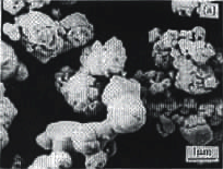
Wet chemical coatings can be achieved by physical or chemical bonding between different materials. As for the carbide powder used in the experiment, the particle size is on the order of micrometers, the surface defects of the particles are large, the specific surface area is large, and the activity is high. It can be seen by scanning electron microscopy (Fig. 1(a)) that the surface of the powder particles is smooth and has no angular edges, and a large number of agglomerated structures are formed between each other. After the powder is subjected to dilute acid impregnation treatment, the oxide on the surface of the particles is removed, and a large number of dangling bonds are formed on the surface layer. In order to achieve a steady state with lower energy, the dangling bonds on the surface of the powder adsorb moisture to form a structure of W-HO (taking WC as an example).
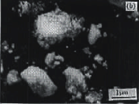
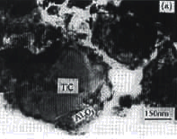
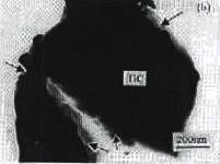
In the boehmite sol, the size of the colloidal particles is nanometer-scale, with a large specific surface area, and its adsorption capacity is stronger, only because the colloidal particles adsorb ions with the same kind of charge and mutually repel each other to form a uniform and stable Suspension system. When the powder is mixed with the sol, the intervention of the powder destroys the ionic atmosphere of the colloidal particles, and the size of the powder differs greatly from that of the colloidal particles, so that the colloidal particles are easily adsorbed on the surface of the powder. At this time, Al-OR (R is an isopropanol group) and Al-OH in the colloid are bonded to W-OH by hydrogen bonding to form a strong adsorption layer. Subsequently, the partially hydrolyzed alcoholate in the coating undergoes a condensation reaction with -OH on the surface of the substrate to form a chemical bond structure of Al-OW. After the dried coating powder is ball milled for a long time, the coating does not fall off, which means that the bonding of the coating to the substrate is quite strong, and the two are mainly bonded in the form of chemical bonds instead of physical adsorption. This bond-bonded form provides a high bond strength between the coating and the powder to substantially maintain the integrity of the coating after sintering and to form a good interface between the coating and the matrix particles. Figure 1 (b) is a sintered coating powder. It can be seen that, compared with Fig. 1(a), since a ceramic coating has been formed, the surface morphology of the powder changes greatly, the coating is thin, the thickness is not uniform, and the coating particles are more uncoated. The surface of the particles is slightly rough, but the coating is fairly complete with no cracks or flaking. Figure 2 is a TEM photograph of the TiC powder coating before and after pre-sintering. Before pre-sintering (Fig. 2(a)), the coating is amorphous boehmite. The structure is loose and loose, the surface is undulating, and there are obvious traces of colloidal adhesion, and the coating is relatively thick. The bond between the layers of the particles is very serious. In addition, some scattered coating materials can be seen from Fig. 2(a), which are formed during the dispersion of the powder, but at the same time the coating remains relatively intact. After sintering (Fig. 2(b)), the coating is thinner (the arrow points to a more obvious coating), the surface and interface are more tidy and clear, the structure is more dense, and the combination of coating and powder surface is also Better, there are no visible gaps and holes in the interface, but the bond strength between the coating and the powder is significantly reduced. During the dispersion process, the coating on some surfaces has fallen off, and the bond between the coating powder particles is also weakened. . Only a small portion of the coating of the two particles is stuck together. In the experiment: the choice of matrix material has an important impact on the properties of the coating powder material. The materials fired from YT14, YW1 and YG6 cemented carbides as powder matrix are labeled as FYT, FYW and FYG, respectively. There are many micro-cracks inside, and the mechanical properties are relatively poor. It is difficult to grind into bending strength samples. Based on the physical matching and chemical compatibility of the materials, the proportion of carbides in the matrix powder was adjusted, and two powder bases with TiC and (WC, TiC) as the main components were obtained. The two coated powder materials FTC1 and FTC2 produced showed good mechanical properties. The mechanical properties of several coated powdered carbide materials are listed in Table 1, respectively, and the properties of two self-made alumina-based ceramic tool materials are also listed for comparison. The hardness of the two coated powder materials is much higher than that of the general cemented carbide, and the strength is slightly lower. The flexural strength of FTC2 is up to 1100 MPa, which is close to the level of YT15 cemented carbide. The performance of FTC1 and FTC2 is similar to that of the two ceramic tool materials LT55 and SG4. PTC1 and SG4 also have higher hardness, but the strength of FTC1 is 50MPa higher than the average of SG4, and the hardness of FTC2 is close to that of LT55. It is about 80 MPa higher than the LT55. In addition, the fracture toughness of both FTC1 and FTC2 is significantly higher than that of LT 55 and SG4.
In the sintering process of the composite material, when the carbide powder contains impurities, the impurity ions are more likely to be enriched at the grain boundary due to the difference in size or electricity price, and a certain amount of action is exerted on the movement of the grain boundary, so-called Impurity pinning effect. When the carbide powder is coated with a layer of Al 2 O 3 , the Al 2 O 3 coating hinders the movement of the carbide grain boundaries, and the carbide grain boundaries move forward, and the Al 2 O 3 coating must be overcome. The resulting resistance, while the grain boundary of Al 2 O 3 is moving forward, the carbide particles play a role in pinning. As a result of this mutual restraint, the grain of the material is refined, and the destruction of the brittle material is mainly along the crystal fracture. When the crack propagates along the grain boundary, the finer the grain of the material, the more the curve of the crack expands, and the longer the extended path, the more energy it can consume. In addition, the initial crack size of the general material is equivalent to the grain size, so the finer the grain, the smaller the initial crack size, which combines the effects of both, because the coating retards the growth of the grain during the sintering process. Therefore, as long as the initial size of the powder is small, a fine grain material with high strength and fracture toughness can be obtained (Fig. 2). In this coated powder material, the ideal state is that Al 2 O 3 completely coats the carbide, and the sintering behavior between the particles occurs only between Al 2 O 3 /Al 2 O 3 and Al 2 O 3 /metal The carbide particles are not in contact with each other, but are evenly separated by Al 2 O 3 . This is similar to the case of single material sintering, which is more conducive to the formation of a high density structure, of course, the actual situation is much different. Still a case of composite sintering. But from another point of view, Al 2 O 3 is used as an additive. Since it is introduced in the form of liquid phase dip coating, it is more uniformly distributed in the matrix material, and the coating powder is not pre-sintered. The interface between Al 2 O 3 and carbide has a higher strength. The increase in interface strength greatly increases the number of transgranular cracks in the material failure. In Fig. 3, the fracture of the FTC1 material has a clear cleavage step, and some of the grain sections have slip lines, which are obviously characterized by transgranular fracture. The formation of a large number of transgranular fractures consumes the energy of crack propagation and improves the strength and fracture toughness of the material.
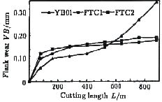
In order to test the effect of the new tool materials, comparative experiments were carried out with ordinary cemented carbide tools, ceramic tools and CVD Al 2 O 3 ceramic coated tools. Figure 4 is the flank wear of the tool FTC1, LT55 and YT15 when cutting hardened T10A tool steel under the cutting conditions of v = 75m / min, f = 0.1mm / r, a p = 0.15mm. It can be seen from the figure that under such conditions, due to the hard material of the workpiece, when the cutting length is 530m, the tool wear after YT15 has reached 0.58mm, and the cutting cannot be continued, while the cutting length of LT55 and FTC1 is 2650m, the rear knives The wear of the face is only about 0.3mm, and the wear of the two is similar. The wear of the FTC1 is slightly less than that of the LT55. Figure 5 is the flank wear of YB01, FTC1 and FTC2 when cutting hardened T10A tool steel under the cutting conditions of v=75m/min, f=0.1mm/r, a p =0.15mm. It can be seen that when cutting hardened materials, the FTC1 and FTC2 coatings are thinner, so the wear amount is larger than YB01 in the initial wear stage, but the powder coating material wears evenly and stably after entering the normal wear stage, and the normal wear of YB01 The stage is relatively short. After the cutting length reaches 520m, it enters the sharp wear stage. This is mainly because the cemented carbide coating of the blade has been basically worn away at this time, and the efficiency is also greatly reduced. In addition, YB01 has a shell-like peeling of the rake face during the cutting process, which may be due to the failure of the coating to be crushed when the cutting force is large, thereby reducing the effectiveness of the coating. FTC1 and FTC2 generally do not break when the cutting speed is low. After the YB01 has a knife face wear of 0.3 mm, the coating no longer functions due to cutting. The tip of the blade becomes dull, the vibration during cutting increases, and the machined surface becomes very rough, making it almost impossible to cut. In this way, the life of the new coated tool is at least twice as long as YB01. 4 ConclusionA thin layer of Al 2 O 3 is coated on the surface of the carbide powder by a sol-gel method, and the coating and the substrate are mainly bonded by a chemical bond; the tool material sintered by using the composite powder is fine and uniform. It has high hardness and high strength, and its fracture form is mainly based on intergranular fracture, and there is a considerable amount of transgranular fracture. This cutting tool has similar cutting performance to ceramic tools when cutting hardened materials. For ordinary carbide tools and A12O3 coated tools. It shows a good comprehensive performance and is a new type of tool material with great development potential. | ||||||||||||||||||||||||||||||||||||||||||||||||||||
Melamine Blockboard,Melamine Board Vs Blockboard,Melamine Faced Blockboard,Melamine Vs Blockboard
LINYI JIUHENG IMPORT AND EXPORT CO.,LTD , http://www.jiuhengwood.com
